SPI Pixel Strip/Dot controller: controls up to 4 universes of LED pixels over two outputs featuring standalone mode.
⚠️ Safety
Ensure you are familiarized with all key information within this guide and other relevant ENTTEC documentation before specifying, installing, or operating an ENTTEC device. If you are in any doubt about system safety, or you plan to install ENTTEC device in a configuration that is not covered within this guide, contact ENTTEC or your ENTTEC supplier for assistance.
⚠️ Heads up: ENTTEC’s return to base warranty for this product does not cover damage caused by inappropriate use, application, or modification to the product.
⚡ Electrical safety
- This device must be operated in accordance with applicable national and local electrical and construction codes.
- This device can be damaged by excess voltage outside the operating range defined within this products datasheet.
- To reduce the risk of fire or electrical faults do not exceed the ratings and limitations defined in the product datasheet or this guide.
- Ensure there are no opportunities for cables to short circuit and cabling cannot be snagged or pulled.
- Do not over stretch cabling to the device’s connectors and ensure that cabling does not exert force on the PCB.
- Isolate your installation from power immediately if accessories power cables or connectors is in any way damaged, defective, shows signs of overheating or are wet.
- Remove power from this product during cleaning or when it is not in use.
- Do not connect this device to a dimmer pack or mains electricity.
- Do not connect any of this device’s 0V, V- or GND connectors to earth.
- Ensure your installation is protected from short circuits and overcurrent.
- Ensure all connections are complete and secure before providing power to the device.
⚠️ System Planning and Specification
- To contribute to an optimal operating temperature, where possible keep this device out of direct sunlight.
- This unit has an IP20 rating and is not designed to be exposed to moisture or condensing humidity.
- Ensure this device is only operated within the specified ranges within the product datasheet.
⚠️ Protection from Injury During Installation
- Always use suitable personal protective equipment when installing ENTTEC products.
- Once installation is completed, check that all hardware and components are securely in place and fastened to supporting structures if applicable.
⚠️ Installation Safety Guidelines
- This device is convection cooled, ensure it receives sufficient airflow so heat can be dissipated.
- Do not cover the device with insulating material of any kind.
- Do not operate the device if the ambient temperature exceeds that stated in the device specifications.
- Do not cover or enclose the device without a suitable and proven method of dissipating heat.
- Do not install the device in damp or wet environments.
- Do not modify the device hardware in any way.
- Do not use the device if you see any signs of damage.
- Do not handle the device in an energized state.
- Do not crush the device during installation.
- Do not sign off a system without ensuring all cabling to the device and accessories has been appropriately restrained, secured and is not under tension.
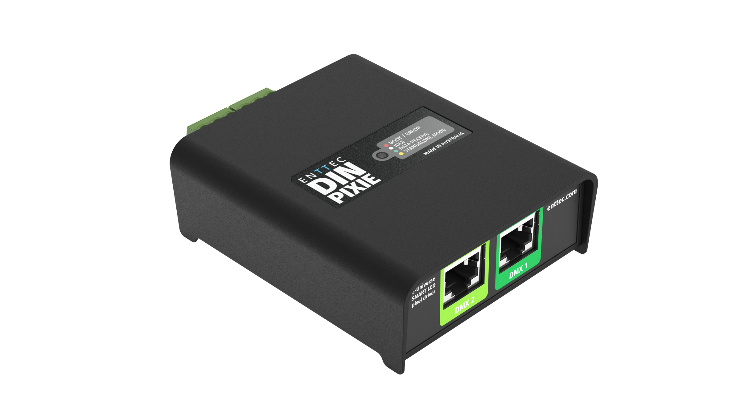
Hardware Feature
- Pluggable screw terminal output connectors.
- Robust USB type-B connector.
- Wide (5-48VDC) operating voltage - power from the same source as your pixels.
- All ports feature ESD surge protection and resettable fuses to block external faults & electrical noise propagation through control infrastructure.
- Forward-facing RGB LED status indicator.
- Surface mount or TS35 DIN mount (using provided DIN Clip accessory)
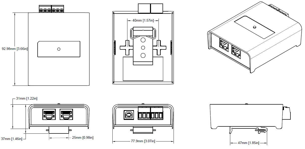
Physical Dimensions
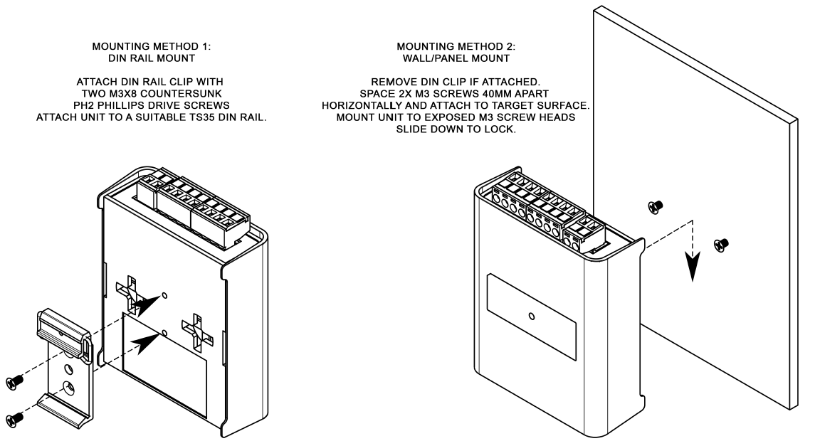
Mounting Methods
⚠️ Note: The surface mount tabs have been designed to hold the weight of the DIN PIXIE only, excess force caused by cable strain can cause damage.
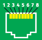
RJ45 Pin Out to DMX Input
The DIN PIXIE features two RJ45 ports for DMX Input.
- Pin 1: Data +
- Pin 2: Data –
- Pin 7/8: Ground
- Pin numbering in accordance with ANSI E1.27-2
⚠️ Note: Label any RJ45 DMX connector and DO NOT connect it to non-DMX ports (i.e. Ethernet Switches). Connecting incompatible systems could result in permanent damage to DIN PIXIE and similar equipment.
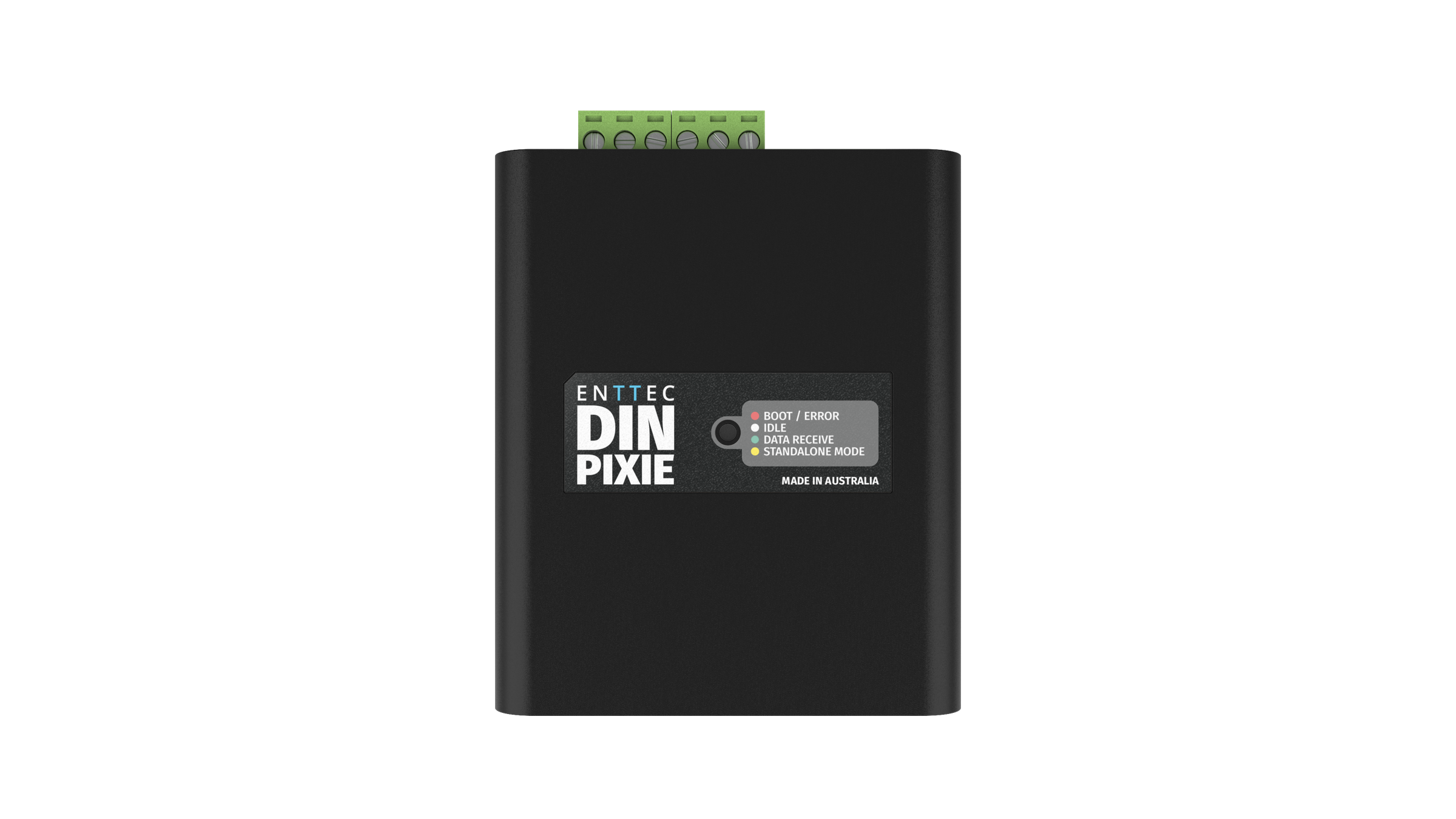
LED Status Indicator
The DIN PIXIE comes with a LED indicator that display different status:
| LED Colour | Status |
|---|---|
| Red | Boot/Error |
| White | Idle |
| Green | Data Receive |
| Yellow | Standalone |
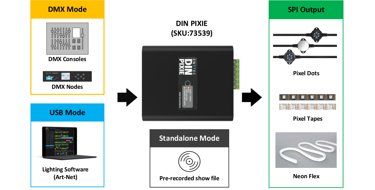
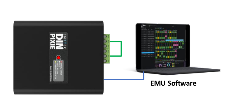
Application Diagram
Wiring Diagrams
⚠️ Note: Connection via USB port will only power DIN PIXIE.

Functional Feature
- Operate between USB Mode, DMX Mode or Standalone Mode.
- 2U pixel control when receiving 1U DMX512 per port in DMX Mode.
- 4U pixel control when recording or using live input in USB Mode.
- Convert received data into over 20 SPI protocols for pixel strips and dots.
- Allow creation of custom pixel protocols. (Criteria apply, see ‘Custom Protocol Creation Guide’ document)
- Configurable DMX start address and pixel grouping function to minimise control channel requirements.
- Standalone show playback using inbuilt flash memory (4000 frames [~100 seconds]).
- Option to play a show on DMX loss or blackout output.
- Configurable and updatable via USB Type-B.
- DMX input on RJ45 connectors (ANSI E1.27-2).
- Test output sequences via EMU software eliminating the need for external data sources.
- Backward compatible with the API for USB to SPI control.
USB Mode
Priority: High – Data from the USB will take priority over DMX and Playback data.
In USB mode, the DIN PIXIE is connected to a computer via the USB Type-B port. Users can configure and manage the device using ENTTEC's EMU software. (More details available in the 'EMU Software' section of this guide)
USB mode is useful for recording standalone shows or sending test data during installation and lighting design. In USB Mode, DIN PIXEL unlocks its full potential, offering 4U pixel control.
ENTTEC also provide an API for the DIN PIXIE, allowing users with programming expertise to integrate DIN PIXIE controls into their software applications. Visit website for more information from API guide document.
DMX Mode
Priority: Medium – Incoming Data from the DMX ports will take priority over Playback data. DMX data will be overridden by USB data.
In DMX mode, DIN PIXIE is connected to DMX512 sources via its 2 RJ45 DMX ports. A single DMX Universe (512 channels) can be received from each DMX port. As a result, in DMX Mode, DIN PIXIE efficiently converts 2 DMX Universes into 2U SPI pixel output.
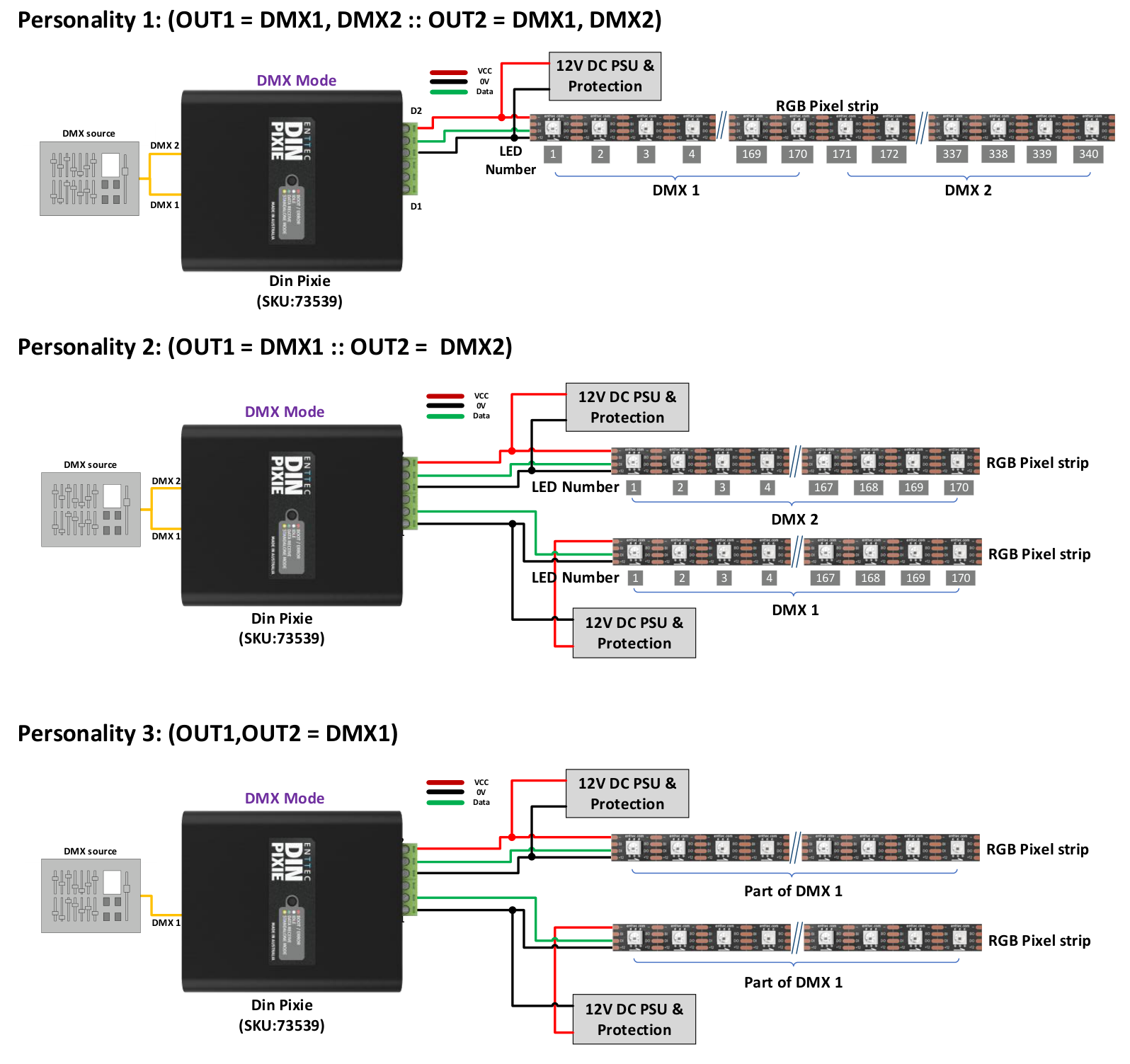
DIN PIXIE offers flexibility in controlling its output through four 'Personalities' within the EMU Software. This feature facilitates precise data distribution across its 2 output ports, catering to a range of specific scenarios and requirements.
| Personality | OUTPUT 1 | OUTPUT 2 | Total pixel control |
|---|---|---|---|
| Personality 1 – Basic Combined | DMX1, DMX2 | DMX1, DMX2 | 340 RGB/128 RGBW Pixels |
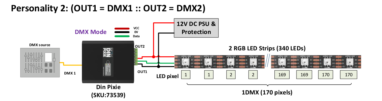
| Personality 2 – Basic Straight Through | DMX1, DMX1 | DMX2, DMX2 | 340 RGB/128 RGBW Pixels |
| Personality 3 – DMX1 Only | Part of DMX1 | Part of DMX1 | 170 RGB/128 RGBW Pixels |
| Personality 4 – DMX2 Only | Part of DMX2 | Part of DMX2 | 170 RGB/128 RGBW Pixels |
Application Example
Standalone Mode
Priority: Low – Data from the Standalone Mode will be overridden by both USB and DMX Data.
In Standalone mode, DIN PIXIE offers consistent playback without the need for a computer/external controller.
The DIN PIXIE can either record a sequence from Art-Net or import/export show files across other DIN PIXIEs through EMU software in USB mode.
All configuration and management are handled through ENTTEC EMU SOFTWARE. More details can be found within Standalone this document.
Out of the Box - Factory Default
By default, DIN PIXIE is set as below:
- DMX Personality: Out1=DMX1 :: Out2=DMX2
- DMX start Address: DMX1 starts at 1, DMX2 starts at 1.
- LED Strip Protocol: WS2812B
- Run Show on DMX loss: No
- Blackout Output: No
- Pixel Ordering: RGB
Configuration Software – ENTTEC EMU
ENTTEC offers the EMU Software, a versatile tool for configuring, troubleshooting, testing, and updating the DIN PIXIE. The EMU software is compatible with both Windows and Mac operating systems (up to OS 10.13 or later) and can be easily downloaded for free from the ENTTEC website. It provides users with a comprehensive solution to conveniently manage and optimize the functionality of the DIN PIXIE.
Discover the Device
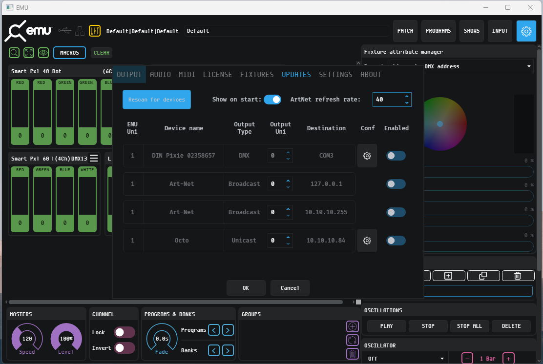
From EMU Software, navigate to the Preference window. The preference window will either pop up upon opening the software or can be accessed by clicking on the gear icon located in the top right corner.
From the Preference Window Output page, click the ‘Scan for devices’ button to search for the DIN PIXIE connected to the computer. When a device is detected, select the gear icon from the device to configure the device.
Config
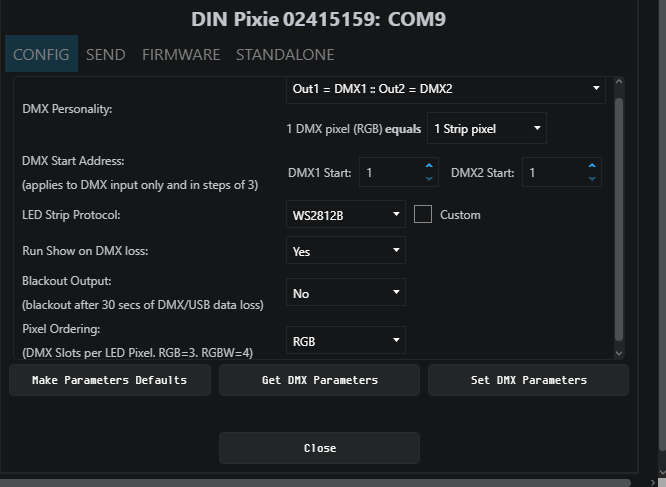
This page provides information about the DIN PIXIE’s state and the ability to configure the device.
- DIN PIXIE Serial Number: the Serial number of the connected device can be found on the top of the configuration window.
- DMX Personality: Choose Personality for precise DMX output distribution.
- 1 DMX pixel equals: Manage up to 2 universes of pixel output per port with reduced data input by grouping multiple LEDs per pixel.
The concept is simple: each pixel corresponds to a set number of LEDs on your strips. For instance, if you opt for 2 LED strips, 1 DMX pixel (170 RGB pixels) can seamlessly control 340 RGB LEDs at its full output, essentially allowing 2 LEDs to be managed per pixel. This streamlined approach optimizes and expands your lighting control.
- Start Address: Offset the DMX start address. The increments are based on Pixel type.
- RGB-8bit increments of 3, allowed value up to 510.
- RGBW-8bit increments of 4, allowed value to 509.
- RGB-16bit increments of 6, allowed value up to 507.
- RGBW-16bit increments of 8, allowed value up to 505.
- DMX Pixel Count: User can configure how 1U pixels are distributed among OUT1 and OUT2 when DIN PIXIE output is set to the personalities of DMX1 or DMX2 only.
- LED Strip Protocol: Choose the relevant protocol to work with your Pixels (more information on this can be found on our website).
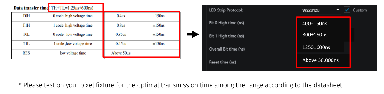
- Custom Protocol: The DIN PIXIE also features custom voltage timing to most of the pixel protocols by ticking ‘Custom’. The custom voltage timing of the chosen pixel protocol can be adjusted according to its datasheet. Visit ENTTEC website to view the ‘Custom Protocol Creation Guide’ document if your SPI protocol is not listed.)
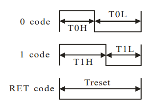
The adjustable custom values are:
- Bit 0 High Time: The voltage high time required to indicate code 0, also known as T0H.
- Bit 1 High Time: The voltage high time required to indicate code 1, also known as T1H.
- Overall Bit Time: The total voltage time for a single bit which can be calculated from TH+TL.
- Reset Time: The total voltage low time required to reset the data transmission between each data batch.
Example: The information required from WS2812B datasheet is the Data Transfer Time as below:
- Run Show on DMX Loss: If no DMX signal is received for 3 seconds, any standalone show saved on the DIN PIXIE will be played back.
- Blackout Output: As the last values received are held on the Pixels, if no DMX or USB signal is received for 30 seconds, the channels will be set to 0.
- Pixel Ordering: By default, the DIN PIXIE is set to RGB. It is recommended that you set this to your Pixel color order. These orders are any combination of RGB and RGBW. If the programming has been done with a different pixel order, you can use this to make the change within the DIN PIXIE, saving having to re-program.
- Make Parameters Defaults: This will resume to default settings.
- Set DMX Parameters: This commands EMU to send the settings to DIN PIXIE.
- Get DMX Parameters: This will retrieve the DIN PIXIE’s current DMX settings.
Send
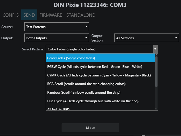
In the Send tab, user is allowed to actively send data to the device for the purposes of design and testing.
Source
This refers to the input data sources which can be sent to the output in the following methods:
- Test Patterns: The users can select the pre-programmed test patterns directly from the ‘Select Pattern’ drop-down list for to test the DMX output.
- Live Art-Net: choosing this option will allow DIN PIXIE to listen for an Art-Net Broadcast through the loopback IP address (127.0.0.1).
Alternatively, users can patch faders in EMU software and drag the desired channels fader to test the DMX output. (Visit ENTTEC website for more information about EMU Software.)
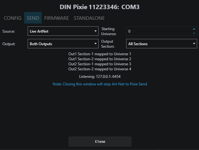
Output
In DIN PIXIE, user can select OUTPUT 1 or OUTPUT 2 as the output destination for the output signal. The First pixel section can control up to 170 RGB or 128 RGBW pixels, and the Second section handles the remaining pixels with the same capacity.
⚠️ Note: DMX Send serves as a troubleshooting tool rather than a full-fledged Lighting Control software. After performing tests, it is important to close the EMU Software before opening your preferred lighting control software. Please note that the DIN PIXIE can only be recognized by one software at a time, as the software establishes a connection with the USB port exclusively.
Firmware
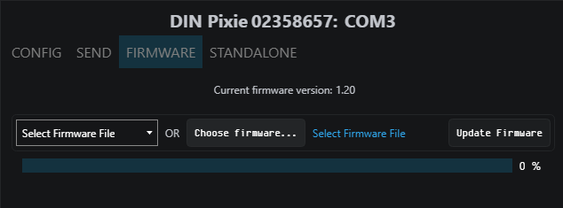
The Firmware update procedure can be used to:
- Update to the latest feature set.
- Reset DIN PIXIE if it ever gets stuck or stops responding. (Eg., Error mode).
The following steps will explain the firmware update procedure:
- Launch the EMU Software on your computer and select from the DIN PIXIE.
- Within Firmware Tab, user can either select the default firmware from the drop-down list or locate a firmware from other source by clicking ‘Choose Firmware’.
- After selecting the firmware file, click on the “Update Firmware” button and let the update proceed. Do not remove the USB cable until the update is complete. The update progress is displayed on the page.
- Once finishes, close the page and the firmware update is completed.
⚠️ Note: Please ensure your EMU Software is updated to the latest version.
Boot
In certain scenarios, you may require access to the boot mode for tasks such as firmware updates or performing a factory reset in case of unstable firmware. To access the boot, follow these steps:
- Wire both data output ports together.
- Connect the DIN PIXIE to a computer via USB cable and the LED will flash in red indicating it is in boot.
- Launch the EMU Software on your computer and select from the DIN PIXIE.
The EMU Software will prompt you to access the boot page for firmware updates or other maintenance tasks.
Standalone
The DIN PIXIE Standalone feature can playback up to 2 Universe sequence/show recorded from DMX port or up to 4 Universe using the ENTTEC EMU Software.
Recordings can be generated either from a DMX console or through DIN PIXIE's USB input by connecting it to a computer using the EMU software. This software facilitates Art-Net internal loopback IP address (127.0.0.1) communication.
The DIN PIXIE only records the changing frames, to maximum the length of the recording.
The playback of the Standalone sequence/show can be triggered from within EMU Software or automatically upon powering up the DIN PIXIE.
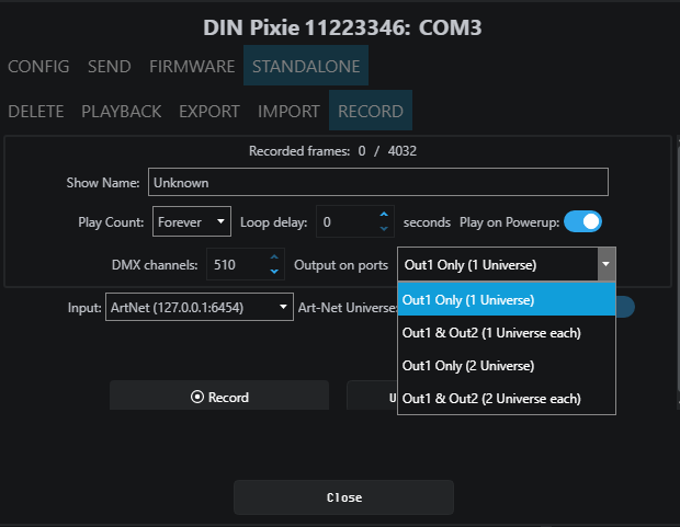
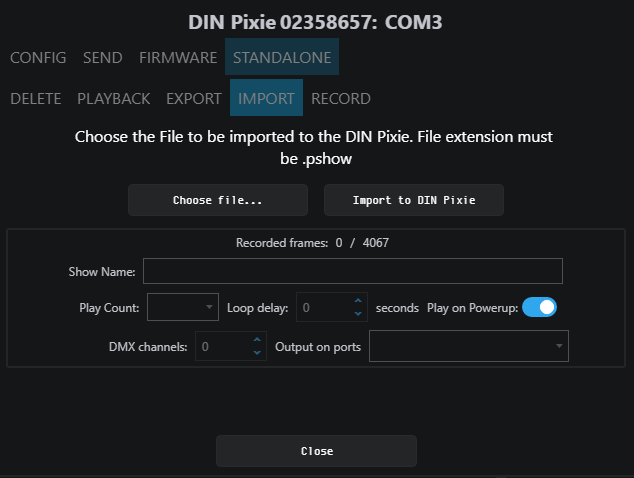
Record
This page allows the input and output configuration for the recording and cannot be modified after it has been recorded. The configuration includes:
- Show Name: Name to identify the show being recorded.
- Play Count: Total number of times the show is played back (from 1 to Forever).
- Loop Delay: The number of seconds delay, between each Loop playback.
- Play on Powerup: If set to Yes, this will automatically start outputting the show as soon as power is supplied to the device.
- DMX Channels: The number of channels to record per DMX Frame (less channels = longer duration of recording)
- Output on ports: specify the outputs on which the recording will be played back..
- Input: Select which source the device will record from.
- Art-Net Universe: refers to the input universe that you are designating for recording. This setting allows you to specify the specific Art-Net universe from which data will be recorded.
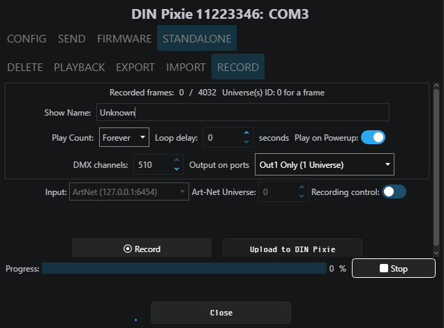
- Recording Control: If you want to use an Art-Net Trigger to start and stop recording, simply set the conditions for the Universe, Channel, and Value that will activate recording. When the received value goes above this threshold, recording starts. If it drops below the threshold, recording stops.
Here is a guide to the recording process:
- Recording Information Display: At the start of the recording process, you'll see details like the number of recorded frames and an estimated show duration. The recording will automatically stop if all available memory is used up.
- Stop Recording: To finish the recording, click on the "Stop recording" button.
- Upload to DIN PIXIE: After stopping the recording, click on the "Upload to DIN PIXIE" button. This action transfers the show file to the memory of the DIN PIXIE. The progress of this transfer will be visible on the page. It's crucial not to interrupt this memory load process to prevent show corruption. Please wait until the upload progress is finalized.
- Upload Completion: Once the upload is complete, the page will indicate that a show is stored on the DIN PIXIE. If you wish to do so, you can revisit the recording page after deleting the stored show.
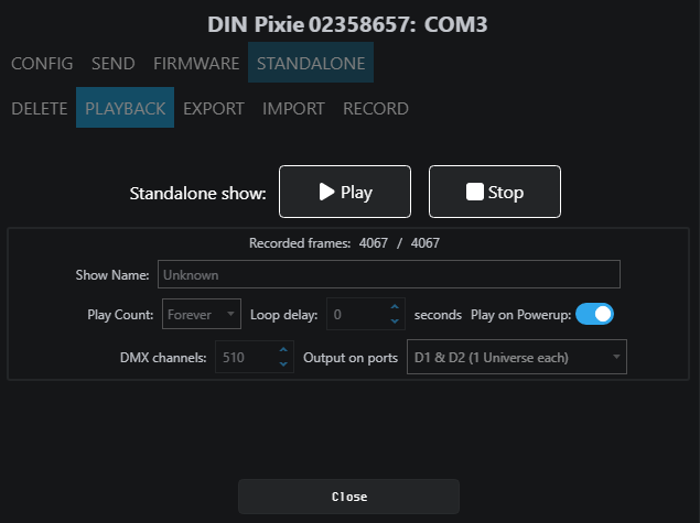
Playback
This page provides information based on the currently recorded sequence/show, reflecting the settings established during the recording process.
Below is a guide to the Playback control options:
- Play: Initiates playback in Standalone Mode
- Stop: Stop the Standalone Mode playback
- Export Show to File: This will download the sequence/show on the DIN PIXIE to a binary file to a computer connected to the DIN PIXIE. This file can then be transferred to another computer if required.
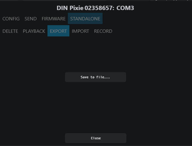
Export
This will export the sequence/show on the DIN PIXIE to a .pshow file on the computer connected to the DIN PIXIE. This export/import process allows the duplication of a show file onto multiple DIN PIXIE devices.
Import
This will import the sequence/show on the DIN PIXIE from a .pshow file on the computer connected to the DIN PIXIE. This export/import process allows the duplication of a show file onto multiple DIN PIXIE devices.
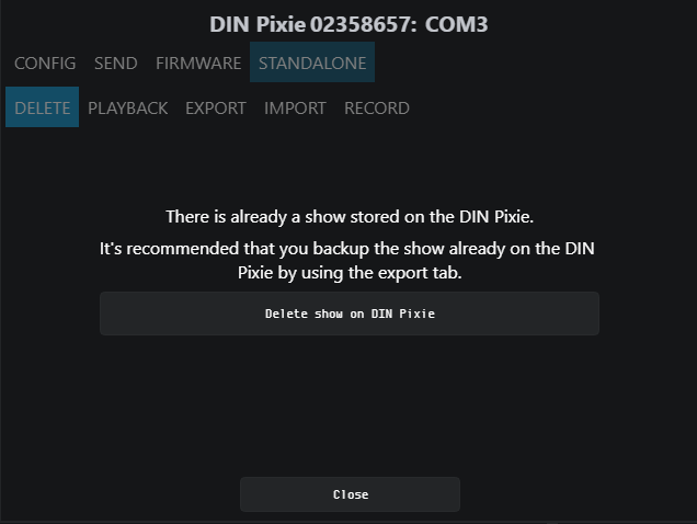
Delete
This will delete the current sequence/show from the DIN PIXIE, ready for a new sequence/show to be recorded. If you do not want the DIN PIXIE to generate any output when powered up, it can be done by erasing the pre-loaded standalone show.
⚠️ Servicing, Inspection & Maintenance
- The device has no user serviceable parts. If your installation has become damaged, parts should be replaced.
- ⚡ Power down the device and ensure a method is in place to stop the system from becoming energized during servicing, inspection & maintenance.
Key areas to examine during inspection:
- Ensure all connectors are mated securely and show no sign of damage or corrosion.
- Ensure all cabling has not obtained physical damage or been crushed.
- Check for dust or dirt build up on the device and schedule cleaning if necessary.
- Dirt or dust buildup can limit the ability for a device to dissipate heat and can lead to damage.
The replacement device should be installed in accordance with all steps within the installation guide. To order replacement devices or accessories contact your reseller or message ENTTEC directly.
Cleaning
Dust and dirt build up can limit the ability for the device to dissipate heat resulting in damage. It’s important that the device is cleaned in a schedule fit for the environment it is installed within to ensure maximum product longevity.
Cleaning schedules will vary greatly depending on the operating environment. Generally, the more extreme the environment, the shorter the interval between cleanings.
⚡ Before cleaning, power down your system and ensure a method is in place to stop the system from becoming energized until cleaning is complete.
- Do not use abrasive, corrosive, or solvent-based cleaning products on a device.
- Do not spray the device or accessories. The device is an IP20 product.
To clean an ENTTEC device, use low-pressure compressed air to remove dust, dirt, and loose particles. If deemed necessary, wipe the device with a damp microfiber cloth.
A selection of environmental factors that may increase the need for frequent cleaning include:
- Use of stage fog, smoke or atmospheric devices.
- High airflow rates (i.e., in close proximity to air conditioning vents).
- High pollution levels or cigarette smoke.
- Airborne dust (from building work, the natural environment or pyrotechnic effects).
If any of these factors are present, inspect all elements of the system soon after installation to see whether cleaning is necessary, then check again at frequent intervals. This procedure will allow you to determine a reliable cleaning schedule for your installation.
Revision History
Please verify your device's serial number and artwork to ensure proper support:
- For DIN PIXIE Revision A (SKU: 73539) with a serial number prior to 2358764, kindly update the firmware up to version 1.2. Note that new firmware versions are not backward compatible with DIN PIXIE Rev A.
- For DIN PIXIE Revision B (SKU: 73539) that is released after serial number 2358765, ensure it is loaded with firmware version 2.0 upward. Additionally, it is required to download and update EMU version 23.10.17.8 at least.
- Make sure to follow the appropriate instructions for your specific DIN PIXIE version to ensure that the firmware is up-to-date and compatible.
Package Contents
- DIN PIXIE
- DIN mounting clip + screws
- USB Type A -> USB 2.0 Type B cable
Ordering Information
For further support and to browse ENTTEC’s range of products visit the ENTTEC website.
| Item | Part No. |
|---|---|
| DIN PIXIE Rev B | 73539 |