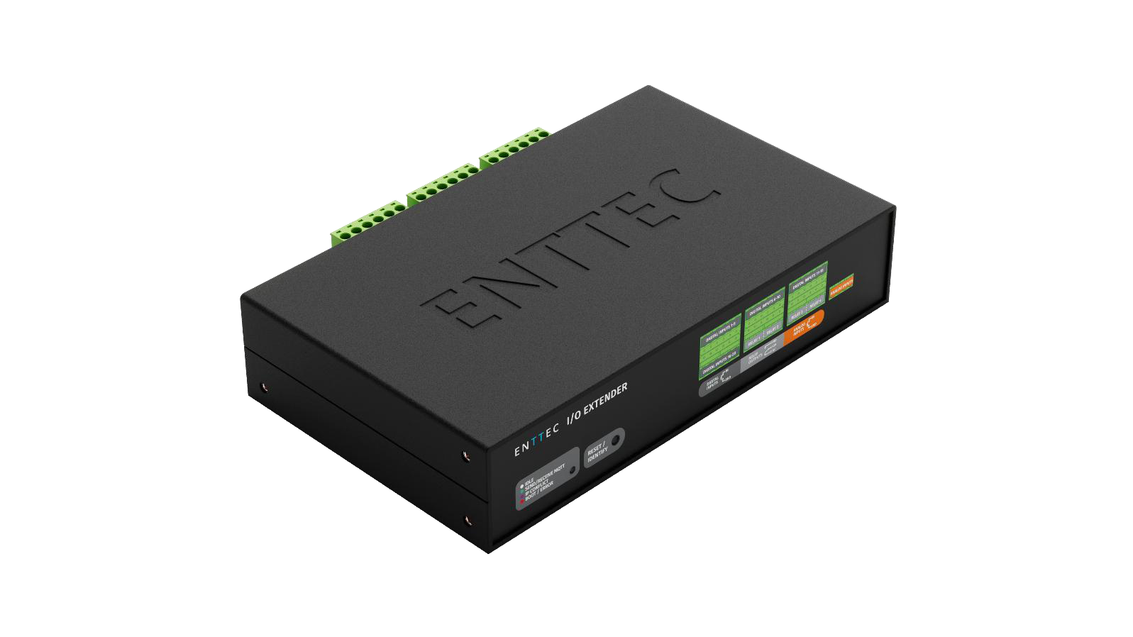
Enhance smart light show control with increased digital inputs, additional relays, and analog inputs.
⚠️ Safety
Ensure you are familiarised with all key information within this guide and other relevant ENTTEC documentation before specifying, installing, or operating an ENTTEC device. If you are in any doubt about system safety, or you plan to install an ENTTEC device in a configuration that is not covered within this guide, contact ENTTEC or your ENTTEC supplier for assistance.
⚠️ Heads up: ENTTEC's return-to-base warranty for this product does not cover damage caused by inappropriate use, application, or modification to the product.
⚡ Electrical safety
- This product must be installed in accordance with applicable national and local electrical and construction codes by a person familiar with the construction and operation of the product and the hazards involved. Failure to comply with the following installation instructions may result in death or serious injury.
- Do not exceed the ratings and limitations defined in the product datasheet or this document. Exceeding can cause damage to the device, risk of fire and electrical faults.
- Ensure that no part of the installation is or can be connected to power until all connections and work is complete.
- Before applying power to your installation, ensure your installation follows the guidance within this document — including checking that all power distribution equipment and cables are in perfect condition and rated for the current requirements of all connected devices and factor in overhead and verify that it is appropriately fused and voltage is compatible.
- Remove power from your installation immediately if any accessory power cable or connector is in any way damaged, defective, shows signs of overheating or is wet.
- Provide a means of locking out power to your installation for system servicing, cleaning and maintenance. Remove power from this product when it is not in use.
- Ensure your installation is protected from short circuits and overcurrent. Loose wires around this device whilst in operation could result in short circuiting.
- Do not over-stretch cabling to the device's connectors and ensure that cabling does not exert force on the PCB.
- Do not 'hot swap' or 'hot plug' power to the device or its accessories.
- Do not connect any of this device's V- (GND) connectors to earth.
- Do not connect this device to a dimmer pack or mains electricity.
⚠️ System planning and specification
- To contribute to an optimal operating temperature, where possible keep this device out of direct sunlight.
- Any twisted-pair, 120 Ω, shielded EIA-485 cable is suitable to transmit DMX512 data. The cable should be suitable for EIA-485 (RS-485) with one or more low-capacitance twisted pairs and overall braid and foil shielding. Conductors should be 24 AWG (7/0.2) or larger for mechanical strength and to minimise volt drop on long lines.
- A maximum of 32 devices on a DMX line before re-generating the signal using a DMX buffer / repeater / splitter.
- Always terminate DMX chains using a 120 Ω resistor to stop signal degradation or data bounce-back.
- The maximum recommended DMX cable run is 300 m (984 ft). ENTTEC advises against running data cabling close to sources of electromagnetic interference (EMF) — e.g. mains power cabling or air-conditioning units.
- This device has an IP20 rating and is not designed to be exposed to moisture or condensing humidity.
- Ensure this device is operated within the specified ranges within its product datasheet.
⚠️ Protection from injury during installation
- Installation of this product must be performed by qualified personnel. If ever unsure, always consult a professional.
- Always work with a plan of the installation that respects all system limitations as defined within this guide and product datasheet.
- Keep the I/O Extender and its accessories in its protective packaging until final installation.
- Note the serial number of each I/O Extender and add it to your layout plan for future reference when servicing.
- All network cabling should be terminated with an RJ45 connector in accordance with the T-568B standard.
- Always use suitable personal protective equipment when installing ENTTEC products.
- Once installation is completed, check that all hardware and components are securely in place and fastened to supporting structures if applicable.
⚠️ Installation safety guidelines
- The device is convection-cooled — ensure it receives sufficient airflow so heat can be dissipated.
- Do not cover the device with insulating material of any kind.
- Do not operate the device if the ambient temperature exceeds that stated in the device specifications.
- Do not cover or enclose the device without a suitable and proven method of dissipating heat.
- Do not install the device in damp or wet environments.
- Do not modify the device hardware in any way.
- Do not use the device if you see any signs of damage.
- Do not handle the device in an energised state.
- Do not crush or clamp the device during installation.
- Do not pull power from the device whilst in operation.
- Do not sign off a system without ensuring all cabling to the device and accessories has been appropriately restrained, secured and is not under tension.
Functional features
- Expand S-PLAY SP1-1 Controller's I/O capacity for greater control.
- Built-in network switch enables show playback without complex infrastructure.
- Ensures real-time data exchange and synchronised control with S-PLAY SP1-1.
- Easy configuration, with most settings managed via the S-PLAY SP1-1 interface.
- Identify button on web interface to signal physical device LED for fast identification.
Hardware features
- 1U height — half-width form factor.
- 12 to 24 V DC input.
- Dual RJ45 Ethernet ports for daisy-chain connectivity at 10/100 Mbps speeds.
- 20 Digital Inputs (GPI).
- 4 Relay outputs (NC, NO, COM). Max. power throughput 60 W, 2 A, 50 V AC or DC.
- 2 Analog Inputs, range 0–10 V DC.
- Screw terminal connectors with pluggable terminal blocks.
- Versatile DIN rail, surface, and rack-mounting options.
LED indicator
The LED status indicator is used to determine the I/O Extender's current state:
| LED Colour | I/O Extender Status |
|---|---|
| White | Idle |
| Green | Send / Receive MQTT |
| Purple | IP Conflict |
| Red | Boot / Error |
Wiring diagrams
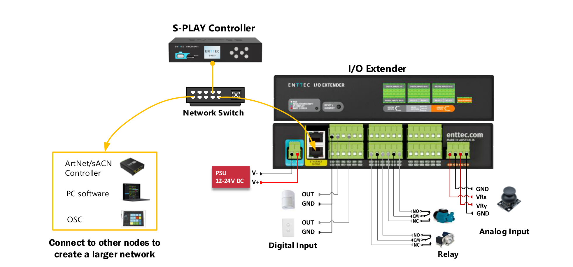
Wire the I/O Extender to the same local network as the S-PLAY SP1-1. Each input and output type — digital inputs, relays, analog inputs — connects to the device's pluggable screw terminal blocks. Power is supplied via the 12–24 V DC screw-terminal connector.
I/O Extender connectivity
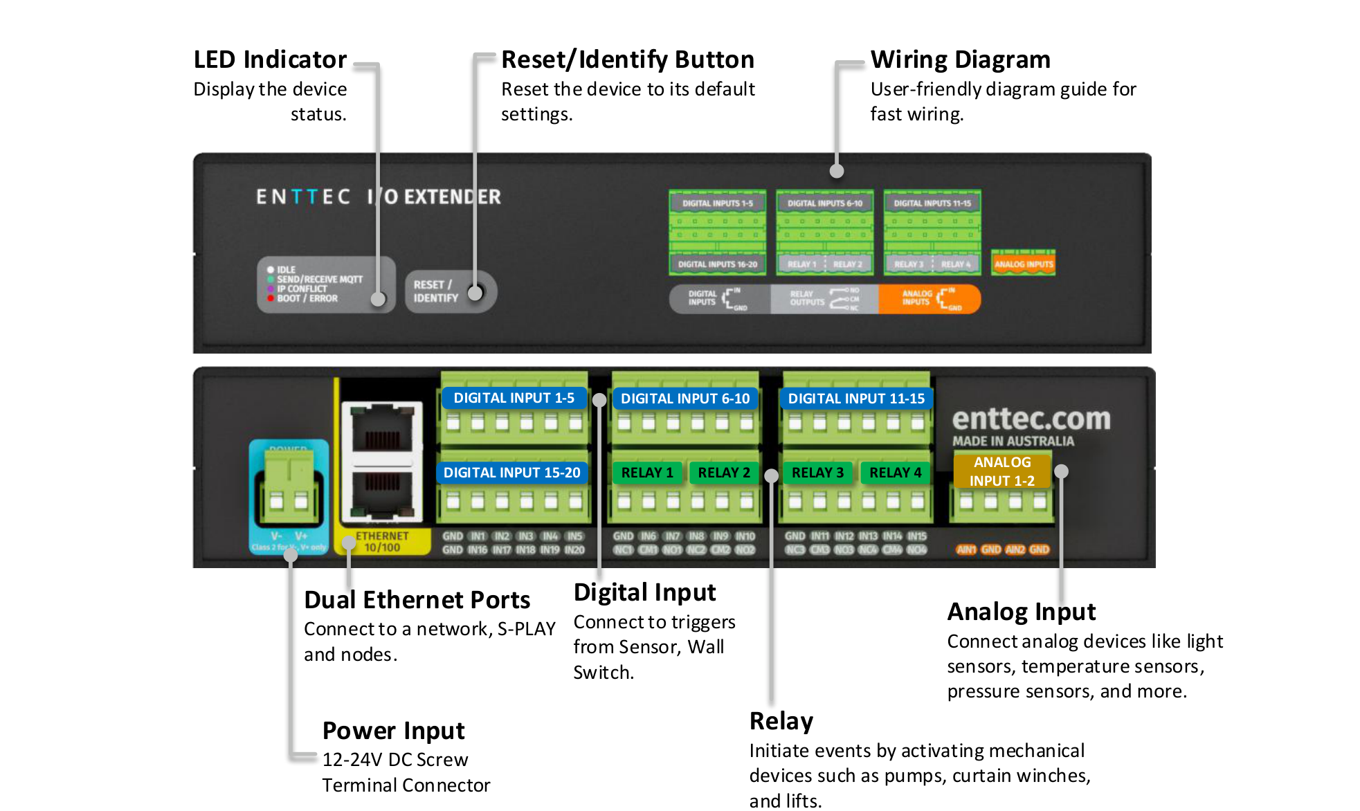
The front and rear panels expose the full I/O surface — dual Ethernet, 12–24 V DC power input, four relay outputs, twenty digital inputs in four pluggable blocks of five, and two analog inputs. The LED indicator and a combined Reset / Identify button sit on the front panel.
Connection to relay
The I/O Extender features relays designed for use with low-power devices and to provide switching logic for higher-power contactors.
To ensure a safe installation it is imperative that the power connected to the I/O Extender's relays is within their operating limits. The I/O Extender's relay specifications are as follows:
| Maximum Current Rating | 2 A |
| Maximum Voltage Rating | 50 V DC |
| Total switchable power of each I/O Extender relay | 60 W |
To calculate the total power your circuit will pass through the relay, multiply the circuit voltage by the current you intend to pass through it. This value must be lower than 60 W. In other words, Voltage × Current ≤ 60 W.
Worked examples
| Example 1 | Example 2 | Example 3 | |
|---|---|---|---|
| Current | 1.2 A | 2 A | 2 A |
| Voltage | 50 V | 30 V | 50 V |
| Maximum Power | 60 W | 60 W | 100 W |
⚠️ Note: If your application requires mains-power switching or high-current applications, ENTTEC recommends wiring the I/O Extender's relay outputs to connect to the primary coil of a DIN-mount high-powered relay or contactor.
Connection to digital input
The I/O Extender's digital inputs detect circuit completion to the I/O Extender's 'GND' (V- terminal) to send triggers.
- The maximum resistance of a cable that can be used to connect a Digital Input to the I/O Extender's GND is 20 Ω.
- ENTTEC recommends a total maximum wire length of 100 m (50 m total distance from the I/O Extender in a loop).
- The longer the cable, the higher its capacitance and likelihood of interference from EMF (electromagnetic interference).
- To ensure a reliable trigger when creating a system, contact should be made for 3 seconds when triggering a digital input.
⚠️ Note: Always run digital input cabling away from mains power or high sources of EMI (e.g. air-conditioning units) to reduce interference.
Connection to analog input
The I/O Extender is equipped with analog inputs capable of detecting and responding to voltage levels ranging from 0 to 10,000 mV (10 V DC). These inputs enhance the S-PLAY SP1-1's flexibility by enabling interaction with external analog joysticks, sensors, controllers, or other devices that output analog signals.
- Use shielded cables to minimise the impact of electromagnetic interference (EMI).
- Before deployment, test the analog input with your device to ensure compatibility and accuracy.
- Verify that the voltage levels align with the intended trigger thresholds in the S-PLAY configuration.
Out of the box
Out of the box, the I/O Extender is factory configured to:
| DHCP | Enabled |
| Static IP | 192.168.0.10 |
| Netmask | 255.255.255.0 |
Networking
The I/O Extender has DHCP IP address enabled by default.
DHCP
When DHCP is enabled, and the I/O Extender is on a network with a DHCP server, it requests an IP address on power-up. If the DHCP server is slow or absent, the I/O Extender falls back to the default IP address: 192.168.0.10 with a netmask of 255.255.255.0.
Static IP
When DHCP is disabled, the default Static IP becomes the communication address. Adjust network settings, including Static or DHCP, Netmask, and Gateway within the Settings page on the I/O Extender's web interface. Remember to note the changed Static IP after modification in the web interface.
⚠️ Note:
- When configuring multiple devices on a Static network, ENTTEC recommends connecting one device at a time to the network and configuring a unique IP to avoid IP conflicts.
- When the I/O Extender is set to a static IP, the default gateway must be the same for both the device and your computer for EMU to discover the I/O Extender.
Configuration
Before configuring the I/O Extender, ensure that the S-PLAY SP1-1 controller is upgraded to the latest firmware (Version 3 or above). The S-PLAY SP1-1 serves as the central hub for managing and controlling the I/O Extender functions.
⚠️ Note: Ensure that your S-PLAY SP1-1 is running the latest firmware version, as this setting may not appear in older versions. Updating to the latest firmware will unlock the full functionality of the I/O Extender integration.
The steps below outline how to properly link and configure the I/O Extender with the S-PLAY SP1-1 controller for integrated operation.
- Connect I/O Extender and S-PLAY SP1-1 to the same network. Ensure that both the S-PLAY SP1-1 controller and the I/O Extender are connected to the same local network.
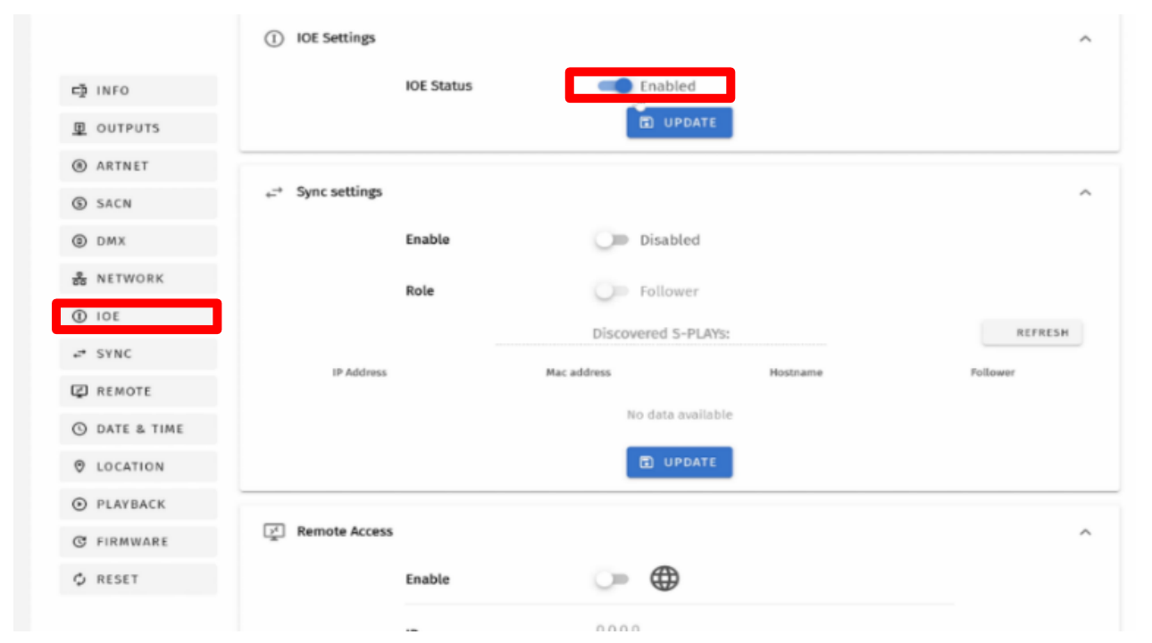
- Enable I/O Extender connection in S-PLAY SP1-1. Open a web browser and enter the IP address of the S-PLAY SP1-1. Navigate to the S-PLAY SP1-1's Settings page and enable IOE functionality.
- Configure the I/O Extender. Open a web browser and enter the IP address of the I/O Extender. Adjust network configurations for the I/O Extender if needed.
- Connect S-PLAY SP1-1 and I/O Extender. In the I/O Extender settings, enter the S-PLAY SP1-1's IP under MQTT Server IP and save changes. The red dot will change to a green dot when the connection is successful.
- Configure I/O settings. Navigate to the S-PLAY's web interface to configure the I/O Extender settings based on your project requirements.
Web interface
Configuring the I/O Extender is done through a web interface that can be brought up on any modern web browser. A Chromium-based browser (e.g. Google Chrome) is recommended.
Identified IP address
If you are aware of the I/O Extender's IP address (either DHCP or Static), the address can be typed directly into the web browser's URL field.
Unidentified IP address
If you are not aware of the I/O Extender's IP address, the following discovery methods can be used on a local network to discover devices:
- ENTTEC EMU software for Windows and macOS (supports macOS 10.13 or later) — discovers ENTTEC devices on the LAN and displays their IP addresses before opting to configure the device by opening the web interface.
- An IP scanning software application (e.g. Angry IP Scanner) can be run on the local network to return a list of active devices.
- Devices can be discovered using Art Poll (e.g. DMX Workshop if set to use Art-Net).
- The device's default IP address 192.168.0.10 is printed on the physical label on the rear of the product.
⚠️ Note:
- As the I/O Extender is hosting a web server on the local network and does not feature an SSL Certificate (used to secure online content), the web browser will display the 'Not secure' warning — this is to be expected.
- The protocols, the controller and the device used to configure the I/O Extender must be on the same Local Area Network (LAN) and within the same IP address range as the I/O Extender. For example, if your I/O Extender is on Static IP 192.168.0.10 (default), then your computer should be set to something such as 192.168.0.20. It is also recommended that all devices' subnet masks are the same across your network.
Top menu

The top menu grants easy access to all I/O Extender web pages, with the active page highlighted in blue. The top-right corner of the window features four installer-friendly buttons:
- Language — choose from available language options, including Chinese and French.
- Dark Mode — view option that presents content on a dark background.
- Save — after making changes in the settings, click Save to apply the adjustments and ensure the changes take effect.
- Identify — press the Identify button and the device's LED will flash blue, allowing quick and accurate device verification.
⚠️ Note: The timer will not restart when pressed consecutively.
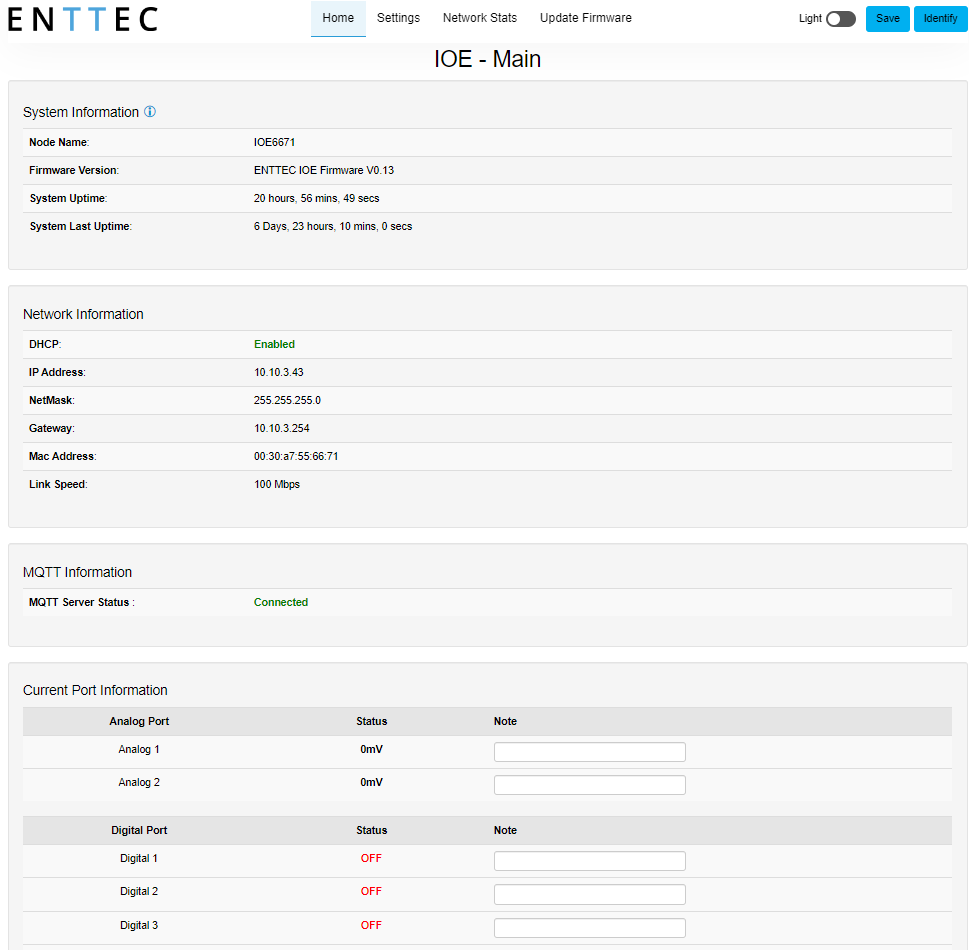
Home tab
The Home page, the default landing page, provides an overview of all input / output activities on the I/O Extender. Users can add notes to the I/Os and remotely test the relays directly from this page.
System information
- Node Name
- Firmware Version
- System Uptime
- System Last Uptime
Network information
- DHCP
- IP Address
- Netmask
- Gateway
- Mac Address
- Link Speed
MQTT information
- MQTT Server Status
Current port information
- Analog Port 1–2
- Digital Port 1–20
- Relay 1–4
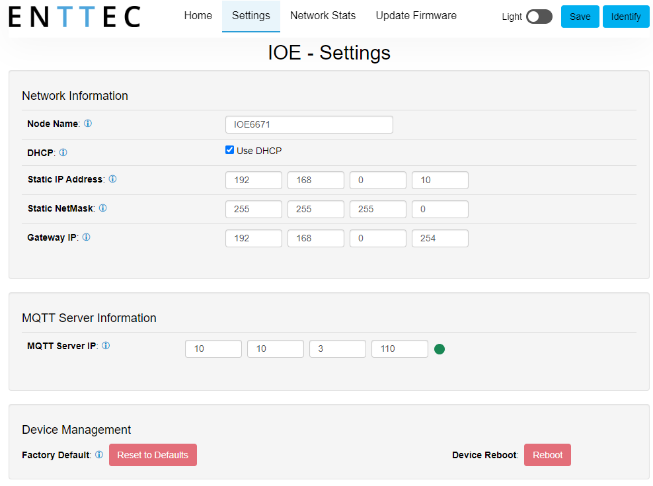
Settings tab

The I/O Extender's network settings and S-PLAY SP1-1 connection can be configured in the Settings tab. Use the Save button in the top-right corner to apply changes — unsaved changes will be discarded.
- Node Name — change Node Name for identification.
- DHCP — enabled by default; the DHCP server is expected to automatically assign an IP address to the I/O Extender. If no DHCP server is available or it is slow to respond, the I/O Extender falls back to 192.168.0.10.
- IP Address / Netmask / Gateway — used to set when DHCP is disabled. These options set the Static IP address, Netmask and Gateway IP settings, which should be compatible with other devices on the network.
- MQTT Server IP — to link the I/O Extender with the S-PLAY SP1-1, provide the S-PLAY SP1-1's IP address in the MQTT Server IP field.
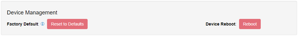
- Reset to Defaults — enables the I/O Extender to be reset to factory defaults through the web interface.
- Reboot — allow up to 10 seconds for the device to reboot. Once the web interface refreshes, the I/O Extender will be ready.
⚠️ Note: Ensure that the S-PLAY SP1-1 has enabled the I/O Extender connection in its settings before proceeding. Refer to Configuration for the full setup.
Network Stats tab
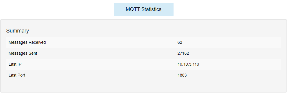
The Network Stats page shows statistics for protocol activity. The information provided is:
- Messages Received
- Messages Sent
- Last IP
- Last Port
Update Firmware tab
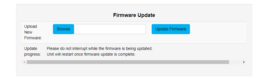
When selecting the Update Firmware tab, the I/O Extender will stop outputting and the web interface boots into Update Firmware mode. It may take a while depending on the network setting. An error message is expected as the webpage is temporarily unavailable in boot mode.
This mode displays basic information regarding the device, including current system information and network settings.
The latest firmware can be downloaded from www.enttec.com. Use the Browse button to select an I/O Extender firmware file from your computer. I/O Extender firmware files have a .bin extension. Click Update Firmware to begin updating.
Once the file has been downloaded, the I/O Extender will begin installing the update. While doing that, the Home page will be greyed out and a message indicating that the update is in progress will be displayed. The site will become accessible again once the update has finished installing.
Reset to factory defaults
The I/O Extender can be reset by either the web interface or the reset button on the device. This resumes the device's settings back to factory default.
Resetting via the web interface
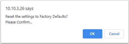
The Reset to Defaults command can be found under the Settings tab of the I/O Extender's locally hosted web interface.
Once the command is pressed, a pop-up will appear as shown in the image below:
Resetting by the reset button
The reset button on the device restores the network configuration of the I/O Extender to factory defaults. To reset to factory defaults, the following procedure must be performed:
- Power off the unit.
- Press and hold the Reset button.
- While holding the Reset button, power up the unit.
- Keep holding the button for approximately 3 seconds.
- Release the Reset button after the LED turns yellow.
- Power cycle the unit.
⚠️ Servicing, inspection & maintenance
- The device has no user-serviceable parts. If your installation has become damaged, parts should be replaced.
- ⚡ Power down the device and ensure a method is in place to stop the system from becoming energised during servicing, inspection & maintenance.
Key areas to examine during inspection:
- Ensure all connectors are mated securely and show no sign of damage or corrosion.
- Ensure all cabling has not obtained physical damage or been crushed.
- Check for dust or dirt build-up on the device and schedule cleaning if necessary.
- Dirt or dust build-up can limit the ability for a device to dissipate heat and can lead to damage.
The replacement device should be installed in accordance with all steps within the installation guide. To order replacement devices or accessories, contact your reseller or message ENTTEC directly.
Cleaning
Dust and dirt build-up can limit the ability for the device to dissipate heat, resulting in damage. It's important that the device is cleaned on a schedule fit for the environment it is installed within to ensure maximum product longevity. Cleaning schedules will vary greatly depending on the operating environment — generally, the more extreme the environment, the shorter the interval between cleanings.
⚠️ Before cleaning:
- Power down your system and ensure a method is in place to stop the system from becoming energised until cleaning is complete.
- Do not use abrasive, corrosive, or solvent-based cleaning products on this device.
- Do not spray on the device or accessories — the device is an IP20 product.
To clean an ENTTEC device, use low-pressure compressed air to remove dust, dirt and loose particles. If deemed necessary, wipe the device with a damp microfibre cloth.
Factors that may increase the need for frequent cleaning
- Use of stage fog, smoke or atmospheric devices.
- High airflow rates (e.g. in close proximity to air-conditioning vents).
- High pollution levels or cigarette smoke.
- Airborne dust (from building work, the natural environment or pyrotechnic effects).
If any of these factors are present, inspect all elements of the system soon after installation to see whether cleaning is necessary, then check again at frequent intervals. This procedure will allow you to determine a reliable cleaning schedule for your installation.
Package contents
- I/O Extender (70096)
- Cat5 Cable (79102)
- Rack-mounting bracket (79161) × 2 pcs + screws × 6 pcs
- Surface / DIN mounting bracket (79162) × 2 pcs + screws × 4 pcs
- DIN Clip (51526) × 2 pcs + screws × 4 pcs
Ordering information
For further support and to browse ENTTEC's range of products, visit the ENTTEC website.
| Item | Part No. |
|---|---|
| I/O Extender | 70096 |
⚠️ Note: Due to constant innovation, information within this document is subject to change.