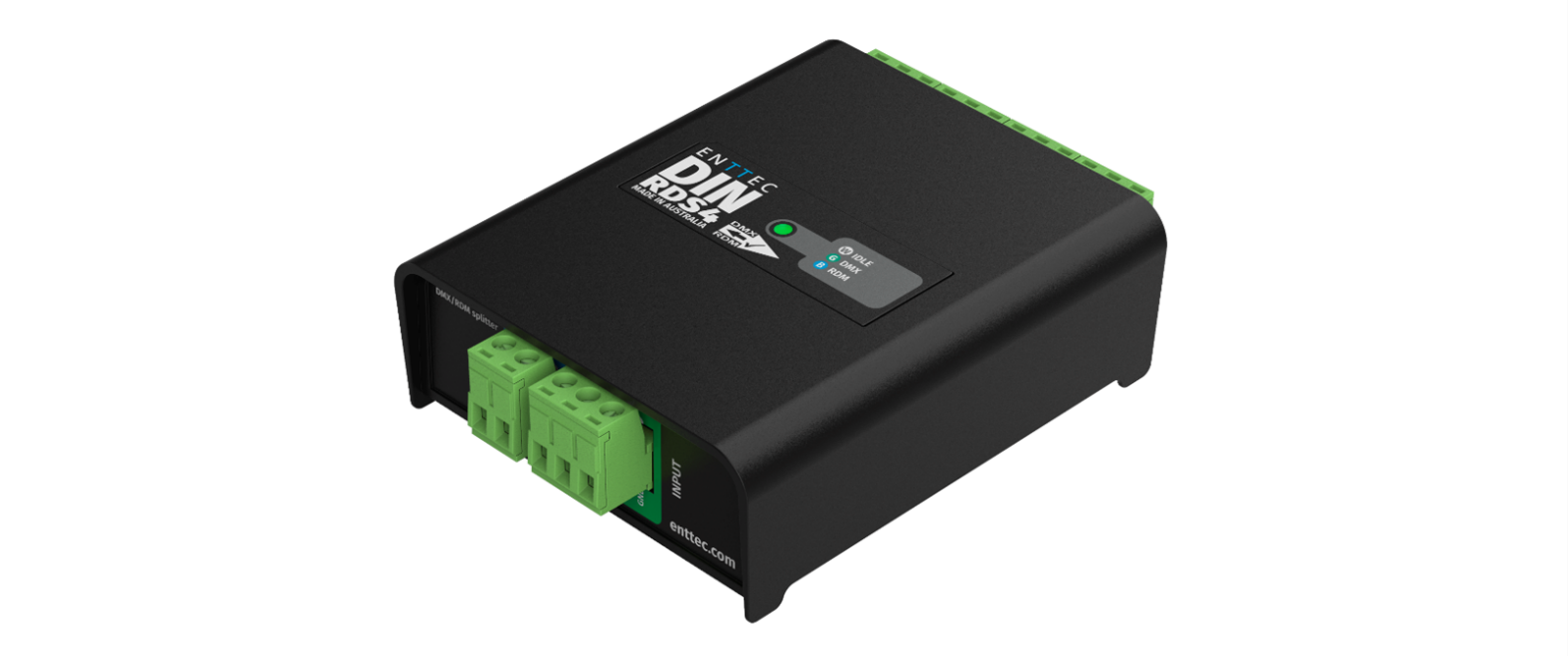
4-way DMX/RDM splitter in compact 4-module DIN-rail form factor.
⚠️ Safety
Ensure you are familiarised with all key information within this guide and other relevant ENTTEC documentation before specifying, installing, or operating an ENTTEC device. If you are in any doubt about system safety, or you plan to install an ENTTEC device in a configuration that is not covered within this guide, contact ENTTEC or your ENTTEC supplier for assistance.
⚠️ Important: ENTTEC's return-to-base warranty for this product does not cover damage caused by inappropriate use, application, or modification to the product.
⚡ Electrical safety
- This product must be installed in accordance with applicable national and local electrical and construction codes by a person familiar with the construction and operation of the product and the hazards involved.
- Do not exceed the ratings and limitations defined in the product datasheet or this document. Exceeding these can cause damage to the device, risk of fire and electrical faults.
- Ensure that no part of the installation is or can be connected to power until all connections and work is complete.
- Before applying power to your installation, ensure your installation follows the guidance within this document — including checking that all power distribution equipment and cables are in perfect condition and rated for the current requirements of all connected devices.
- Remove power from your installation immediately if accessories, power cables or connectors are in any way damaged, defective, show signs of overheating or are wet.
- Provide a means of locking out power to your installation for system servicing, cleaning and maintenance. Remove power from this product when it is not in use.
- Ensure your installation is protected from short circuits and overcurrent. Loose wires around this device whilst in operation could result in short circuiting.
- Do not over stretch cabling to the device's connectors and ensure that cabling does not exert force on the PCB.
- Do not 'hot swap' or 'hot plug' power to the device or its accessories.
- Do not connect any of this device's V− (GND) connectors to earth.
- Do not connect this device to a dimmer pack or mains electricity.
⚠️ System planning and specification
- To contribute to an optimal operating temperature, where possible keep this device out of direct sunlight.
- Any twisted pair, 120 Ω, shielded EIA-485 cable is suitable to transmit DMX512 data to or from the DIN RDS4 MK2. The DMX cable should be suitable for EIA-485 (RS-485) with one or more low-capacitance twisted pairs, with overall braid and foil shielding. Conductors should be 24 AWG (7/0.2) or larger for longer runs.
- A maximum of 32 devices should be used on a DMX line before re-generating the signal using a DMX buffer/repeater/splitter.
- Always terminate DMX chains using a 120 Ω resistor to stop signal degradation or data bounce-back.
- The maximum recommended DMX cable run is 300 m (984 ft). ENTTEC advises against running data cabling close to sources of electromagnetic interference (EMI), e.g. mains power cabling or air conditioning units.
- This device has an IP20 rating and is not designed to be exposed to moisture or condensing humidity.
- Ensure this device is operated within the specified ranges within its product datasheet.
⚠️ Protection from injury during installation
- Installation of this product must be performed by qualified personnel. If ever unsure, always consult a professional.
- Always work with a plan of the installation that respects all system limitations as defined within this guide and product datasheet.
- Keep the DIN RDS4 MK2 and its accessories in their protective packaging until final installation.
- Note the serial number of each DIN RDS4 MK2 and add it to your layout plan for future reference when servicing.
- Always use suitable personal protective equipment when installing ENTTEC products.
- Once installation is completed, check that all hardware and components are securely in place and fastened to supporting structures if applicable.
⚠️ Installation safety guidelines
- The device is convection cooled — ensure it receives sufficient airflow so heat can be dissipated.
- Do not cover the device with insulating material of any kind.
- Do not operate the device if the ambient temperature exceeds that stated in the device specifications.
- Do not cover or enclose the device without a suitable and proven method of dissipating heat.
- Do not install the device in damp or wet environments.
- Do not modify the device hardware in any way.
- Do not use the device if you see any signs of damage.
- Do not handle the device in an energised state.
- Do not crush or clamp the device during installation.
- Do not sign off a system without ensuring all cabling to the device and accessories has been appropriately restrained, secured and is not under tension.
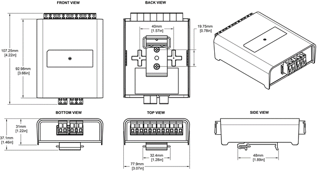
Physical dimensions
Mounting options
The DIN RDS4 MK2 supports two mounting methods:
- TS35 DIN Rail Mount: Attach the included DIN clip accessory and snap onto a standard TS35 DIN rail.
- Surface Mount: Mount directly to a panel or enclosure surface using the integrated surface mount tabs.
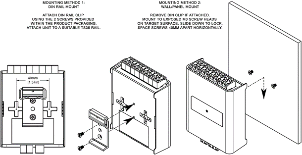
⚠️ Note: The surface mount tabs have been designed to hold the weight of the RDS4 only. Excess force caused by cable strain can cause damage.
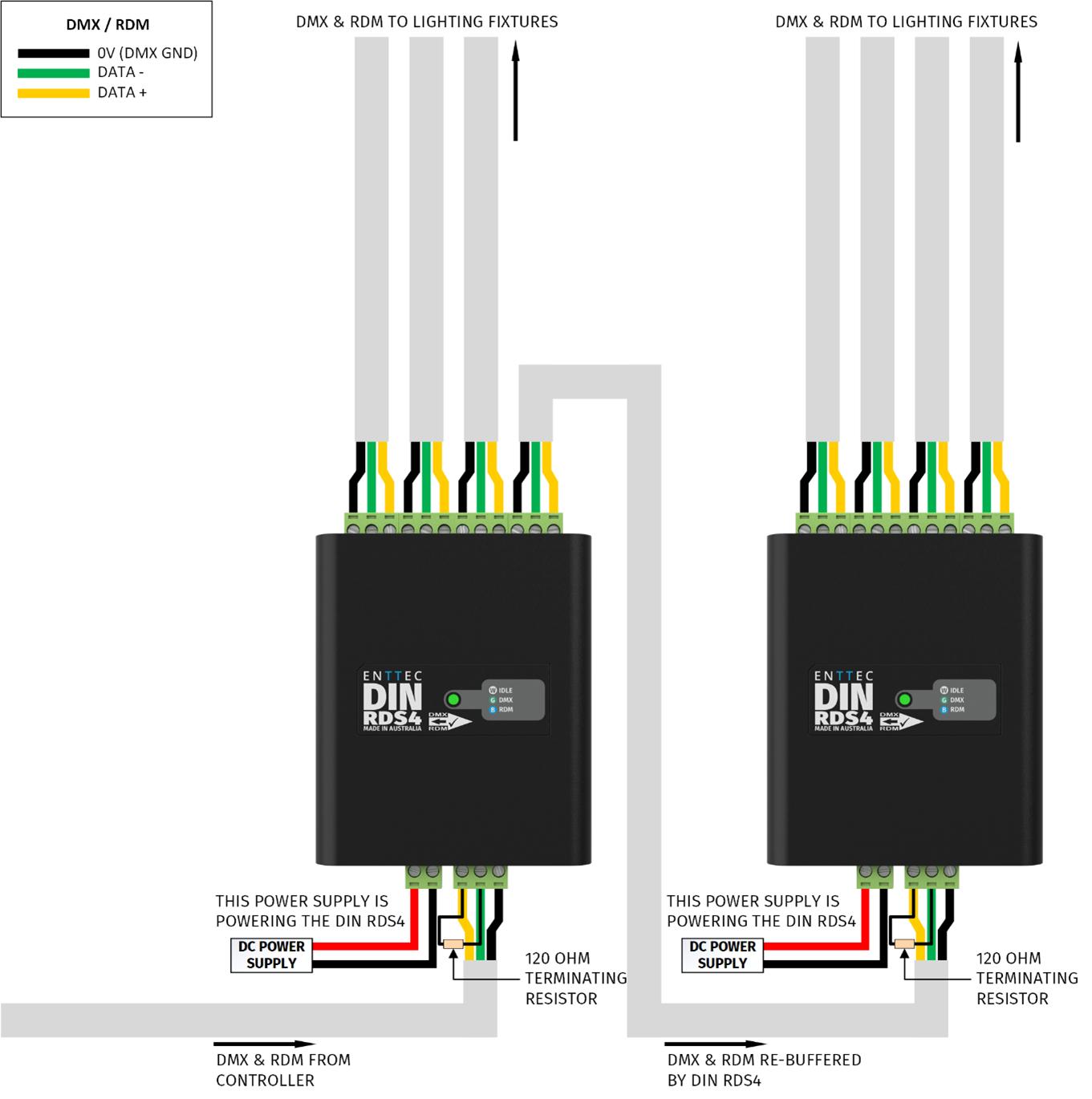
Wiring diagrams
Follow these guidelines when wiring the DIN RDS4 MK2:
- To reduce the likelihood of voltage or EMI being induced on the DMX lines, run control cabling away from mains electricity or devices that produce high EMI (e.g. air conditioning units).
- The maximum cable distance DMX can be run without re-buffering is 300 m (984 ft).
- Never exceed 32 devices in a DMX chain without an intermediary DMX splitter (e.g. another DIN RDS4 MK2).
- Terminate all DMX chains to eliminate signal bounce-back. This can be done by wiring a 120 Ω resistor between Data+ and Data−, or with a DMX terminator.
- To ensure a reliable connection, ENTTEC recommends the use of cable ferrules for all stranded cables connected to the DIN RDS4 MK2's screw terminals.
- When using multiple DIN RDS4 MK2 units to increase the number of DMX input ports, do not double-wire inputs together as a passthrough. Instead, use one of the four outputs to connect to the next RDS4 MK2 input — using the input as a passthrough will likely cause signal degradation.
Functional features
1>4 Splitter
The DIN RDS4 MK2 takes a DMX512-A input from a control source and replicates it onto each of its 4 outputs. This allows more flexible cabling as opposed to running a single long DMX chain from the DMX controller through each fixture (up to 32 DMX devices can be connected per output).
RDM (ANSI E1.20)
The DIN RDS4 MK2 supports the RDM protocol (ANSI E1.20) allowing devices connected to any of its four outputs to communicate back to the DMX controller.
Hardware features
- Forward-facing LED status indicator.
- 1500 V opto-isolation between each port.
- 1× DMX/RDM input.
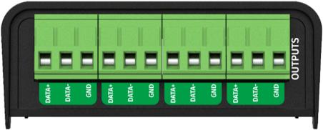
- 4× DMX/RDM outputs.
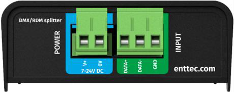
- 1× 2-pin DC power input — Phoenix connector, 7→24 V DC.
- Pluggable terminal blocks.
- Electrically insulated ABS plastic housing.
- Surface or TS35 DIN mount (using included DIN Clip accessory).
LED status indicator
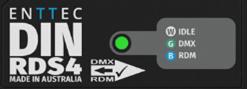
The DIN RDS4 MK2 comes with a forward-facing RGB LED indicator. When in operation, the DIN RDS4 MK2 LED will change between a combination of these states. The LED colour signifies the related activity:
| LED colour | DIN RDS4 MK2 status |
|---|---|
| White | Idle |
| Green | DMX Data Receiving |
| Blue | RDM Activity |
Out of the box
The DIN RDS4 MK2 requires no configuration. Simply wire it up following the wiring diagram within this user manual and add power.
⚠️ Note: The DIN RDS4 MK2 is not provided with a power supply. A separate 7–24 V DC supply must be connected to the 2-pin Phoenix power input.
Screw terminal connectors
⚠️ Servicing, inspection & maintenance
- The device has no user-serviceable parts. If your installation has become damaged, parts should be replaced.
- ⚡ Power down the device and ensure a method is in place to stop the system from becoming energised during servicing, inspection and maintenance.
Key areas to examine during inspection:
- Ensure all connectors are mated securely and show no sign of damage or corrosion.
- Ensure all cabling has not sustained physical damage or been crushed.
- Check for dust or dirt build-up on the device and schedule cleaning if necessary.
- Dirt or dust build-up can limit the ability for a device to dissipate heat and can lead to damage.
The replacement device should be installed in accordance with all steps within this installation guide. To order replacement devices or accessories, contact your reseller or message ENTTEC directly.
Cleaning
Dust and dirt build-up can limit the device's ability to dissipate heat, resulting in damage. Clean on a schedule fit for the operating environment — the more extreme the environment, the shorter the interval between cleanings.
⚠️ Before cleaning: Power down the system and ensure a method is in place to stop the system from becoming energised until cleaning is complete. Do not use abrasive, corrosive, or solvent-based cleaning products. Do not spray the device — it is rated IP20.
To clean an ENTTEC device, use low-pressure compressed air to remove dust, dirt, and loose particles. If necessary, wipe with a damp microfibre cloth.
Factors that may require more frequent cleaning:
- Use of stage fog, smoke, or atmospheric devices.
- High airflow rates (e.g. in close proximity to air conditioning vents).
- High pollution levels or cigarette smoke.
- Airborne dust (from building work, the natural environment, or pyrotechnic effects).
If any of these are present, inspect the system soon after installation, then check at frequent intervals to determine a reliable cleaning schedule.
Package contents
- DIN RDS4 MK2
- TS35 DIN Clip & 2× Torx T10 self-tapping screws
⚠️ Note: The DIN RDS4 MK2 is not provided with a power supply.
Ordering information
For further support and to browse ENTTEC's range of products, visit the ENTTEC website.
| Item | Part No. |
|---|---|
| DIN RDS4 MK2 | 72004 |
⚠️ Note: Due to constant innovation, information within this document is subject to change.